
Specifications
Model Number |
N/A ESNTLUL1502405CDLA |
UL Approvals |
N/A BBGQ: UL1236, CSA22.2 no. 107.2 |
Industry Standards |
N/A CE CSA22.2 No. 107.2 cULus UL Tested UL1236 |
Electrical Connections |
N/A
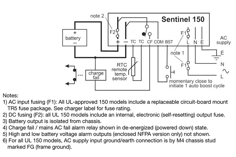 Electrical Connections for Sentinel 150 Automatic Battery Chargers |
Power Supply
Alternate Current (AC) Operating Voltage |
N/A 95 to 250 V |
Operating Frequency |
N/A 47 to 63 Hz |
Direct Current (DC) Charge Output
Direct Current (DC) Nominal Voltage |
N/A 24 V |
Maximum Current Limit |
N/A 5 A |
Voltage Ripple |
N/A <1 % |
Line Regulation |
N/A <2 % |
Load Regulation |
N/A <2 % |
Alarm Outputs
Charge Fail, Mains Alternate Current (AC) Fail |
N/A +DC During Normal Charge 1 x Solid-State Relay Open Circuit During Fault |
| Maximum Current Rating at 30 Direct Current (DC) Voltage (All Relay Outputs)1 | N/A 250 mA |
Standards for Maximum Current Rating at 30 Direct Current (DC) Voltage (All Relay Outputs) |
N/A UL Class 2 |
Alarm Outputs Information |
N/A
Sentinel UL150 models include a self-diagnostic circuit for monitoring charge fail fault conditions (AC supply/fuse failure, DC fuse failure or low/no charge current), with a solid-state relay output for driving a remote alarm or fault annunciator. Enclosed NFPA models have NFPA 110 compliant alarms for AC failure, charge fail, high battery volts and low battery volts. |
Physical
Operating Temperature |
N/A -4 to 140 ºF-20 to 60 ºC |
Relative Humidity |
N/A 20 to 90 % |
Electrical Safety |
N/A 2006/95/EC |
Electromagnetic Compatibility |
N/A 2004/108/EC (EN 61000-6-2, EN 61000-6-4) |
Dimensions
Overall Width (W) |
N/A 4.72 in120 mm |
Overall Height (H1) |
N/A 10.51 in267 mm |
Overall Height (H2) |
N/A 2.76 in70 mm |
Overall Depth (D1) |
N/A 3.74 in95 mm |
Overall Depth (D2) |
N/A 5.12 in130 mm |
Fixing Holes (X) |
N/A 2.50 in63.5 mm |
Fixing Holes (Y) |
N/A 10.04 in255 mm |
Weight |
N/A 2.8 lb1.25 kg |
Standard Output Calibration
Output Calibration Information |
N/A
Calibration figures shown are at 20 ºC. If temperature compensation is enabled and remote SNTL-RTC temperature sensor is connected, output voltage automatically varies by 3 mV per cell per 1 ºC deviation from 20 ºC, within the range -10 to 50 ºC. Increasing temperatures give decreasing outputs; decreasing temperatures give increasing outputs. |
Output Calibration Specification Table |
N/A
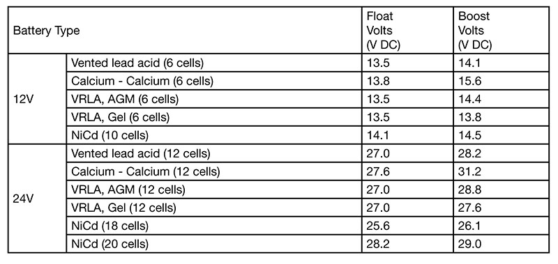 Output Calibration Specification Table for Sentinel 150 Automatic Battery Chargers |
Features
Features |
N/A
AutoBoost provides a temporary increase in output voltage, equalizing the charge between cells and maximizing battery life and capacity. AutoBoost is triggered automatically when the battery falls below a preset voltage or can be initiated manually through a momentary switch input. At the end of the AutoBoost cycle, Sentinel automatically reverts to normal float charge mode, preventing battery over-charge and gassing. |
AutoBoost
AutoBoost |
N/A
AutoBoost provides a temporary increase in output voltage, equalizing the charge between cells and maximizing battery life and capacity. AutoBoost is triggered automatically when the battery falls below a preset voltage or can be initiated manually through a momentary switch input. At the end of the AutoBoost cycle, Sentinel automatically reverts to normal float charge mode, preventing battery over-charge and gassing. |
Temperature Compensation
Temperature Compensation |
N/A
The optimum charge voltage for lead acid and NiCd batteries varies with ambient temperature. Sentinel can be configured to sense battery temperature from a remote sensor and automatically compensate the output charge voltage. |
Installation and Connection
Installation and Connection |
N/A
UL-recognized SNTLUL150 model uses an open frame circuit board and base/heatsink with protected cover, for surface or DIN rail mounting in an existing control panel. UL-listed ESNTLUL150 models use a stainless steel, wall-mounted case. |
Note
Note |
N/A
UL Tested (listed or recognized) to: UL1236 - Battery chargers for charging engine-starting batteries, and CSA22.2 No. 107.2 - Battery chargers. |
- 1 Resistive load


