
Specifications
Model Number |
N/A SNTLUL1502405CDLA |
UL Approvals |
N/A BBGQ: UL1236, CSA22.2 no. 107.2 |
Industry Standards |
N/A CE cRU CSA22.2 No. 107.2 UL Tested UL1236 |
Electrical Connections |
N/A
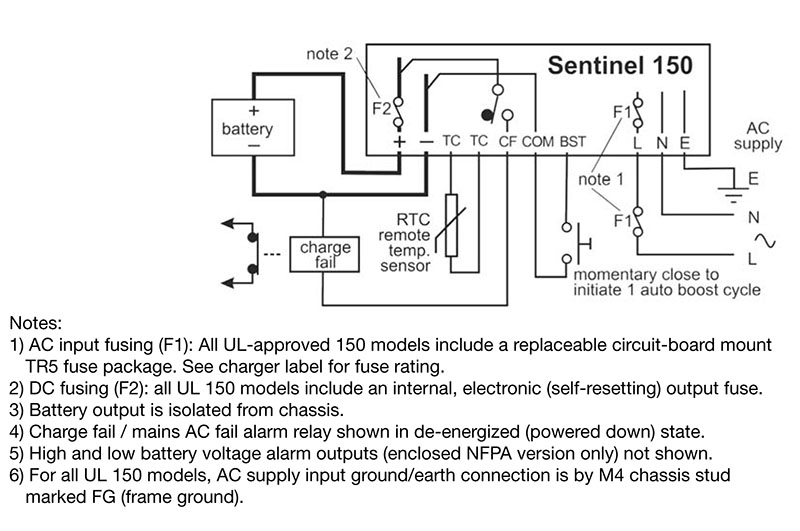 Electrical Connections for Sentinel 150 Automatic Battery Chargers |
Power Supply
Alternate Current (AC) Operating Voltage |
N/A 95 to 250 V |
Operating Frequency |
N/A 47 to 63 Hz |
Direct Current (DC) Charge Output
Direct Current (DC) Nominal Voltage |
N/A 24 V |
Maximum Current Limit |
N/A 5 A |
Voltage Ripple |
N/A <1 % |
Line Regulation |
N/A <2 % |
Load Regulation |
N/A <2 % |
Alarm Outputs
Charge Fail, Mains Alternate Current (AC) Fail |
N/A +DC During Normal Charge 1 x Solid-State Relay Open Circuit During Fault |
| Maximum Current Rating at 30 Direct Current (DC) Voltage (All Relay Outputs)1 | N/A 250 mA |
Standards for Maximum Current Rating at 30 Direct Current (DC) Voltage (All Relay Outputs) |
N/A UL Class 2 |
Alarm Outputs Information |
N/A
Sentinel UL150 models include a self-diagnostic circuit for monitoring charge fail fault conditions (AC supply/fuse failure, DC fuse failure or low/no charge current), with a solid-state relay output for driving a remote alarm or fault annunciator. Enclosed NFPA models have NFPA 110 compliant alarms for AC failure, charge fail, high battery volts and low battery volts. |
Physical
Operating Temperature |
N/A -4 to 140 ºF-20 to 60 ºC |
Relative Humidity |
N/A 20 to 90 % |
Electrical Safety |
N/A 2006/95/EC |
Electromagnetic Compatibility |
N/A 2004/108/EC (EN 61000-6-2, EN 61000-6-4) |
Dimensions
Overall Width (W) |
N/A 4.33 in110 mm |
Overall Height (H) |
N/A 5.31 in135 mm |
Overall Depth (D) |
N/A 3.07 in78 mm |
Fixing Holes (X) |
N/A 3.94 in100 mm |
Fixing Holes (Y1) |
N/A 4.53 in115 mm |
Fixing Holes (Y2) |
N/A 2.26 in57.5 mm |
Weight |
N/A 1.2 lb0.55 kg |
Standard Output Calibration
Output Calibration Information |
N/A
Calibration figures shown are at 20 ºC. If temperature compensation is enabled and remote SNTL-RTC temperature sensor is connected, output voltage automatically varies by 3 mV per cell per 1 ºC deviation from 20 ºC, within the range -10 to 50 ºC. Increasing temperatures give decreasing outputs; decreasing temperatures give increasing outputs. |
Output Calibration Specification Table |
N/A
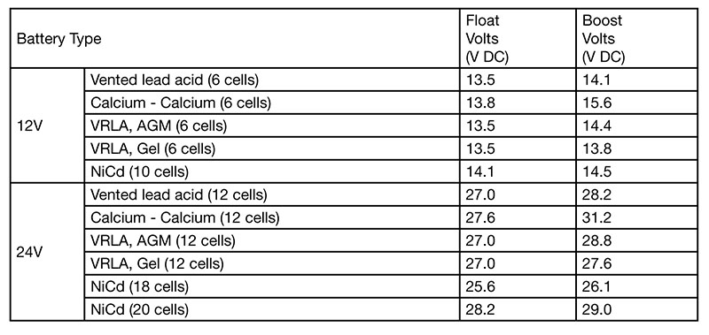 Output Calibration Specification Table for Sentinel 150 Automatic Battery Chargers |
Features
Features |
N/A
All models feature an intelligent, multistage charge regime. During charge recovery mode, the Sentinel gives a constant (maximum) current output. As the battery approaches peak charge, the output reverts to float charge mode, maintaining an optimum cell voltage and supplying additional standing load current up to the rated maximum. Output current is always limited to the rated maximum, even during high load (e.g., engine cranking), short-circuit or reverse polarity connection. |
AutoBoost
AutoBoost |
N/A
The optimum charge voltage for lead acid and NiCd batteries varies with ambient temperature. Sentinel can be configured to sense battery temperature from a remote sensor and automatically compensate the output charge voltage. |
Temperature Compensation
Temperature Compensation |
N/A
The optimum charge voltage for lead acid and NiCd batteries varies with ambient temperature. Sentinel can be configured to sense battery temperature from a remote sensor and automatically compensate the output charge voltage. |
Installation and Connection
Installation and Connection |
N/A
UL Tested (listed or recognized) to: UL1236 - Battery chargers for charging engine-starting batteries, and CSA22.2 No. 107.2 - Battery chargers. |
Note
Note |
N/A
UL Tested (listed or recognized) to: UL1236 - Battery chargers for charging engine-starting batteries, and CSA22.2 No. 107.2 - Battery chargers. |
- 1 Resistive load


